Teyi Gabion Baskets Factory
About Us
gabion manufacturing company
Our products include Gabion Baskets, River Gabion Matresses,Gabion Sacks, Rockfall Nets,Welded Gabions, Gabion Wall , Gabion Cage and other products.
Teyi Gabion Baskets Factory
gabion manufacturing company
Our products include Gabion Baskets, River Gabion Matresses,Gabion Sacks, Rockfall Nets,Welded Gabions, Gabion Wall , Gabion Cage and other products.
Reference
Working at height - Refer to the Health and Safety provisions in Employment Act 1992 regarding the need to take all practicable
steps to ensure safety of workers. Further information of on how to prevent falls from height can be obtained
Material Delivery
Gabions are manufactured with all components mechanically connected during production. All gabions are supplied in the collapsed form, folded and bundled. The bundles are compressed and strapped together at the factory for easy shipping and handling.
Lacing wire is shipped in coils. Ring fasteners are shipped in boxes. Preformed bracing wires are shipped in bundles.
Assembly
Open and unfold each gabion on a flat, hard surface and remove any shipping fold. The gabion boxes shall be assembled individual-
ly, by raising the sides, ends and diaphragms, ensuring that all creases are in the correct position and that the tops of all four sides and the diaphragms are even. (Fig 1)
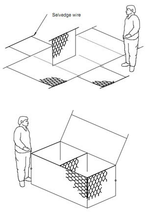
Figure 1
Connect the back and the front panels of the gabion to the end panels and center diaphragms. The top corner of the end panels and center diaphragms have an extended selvedge wire extending approx. 0.1 m out from the corner edge. Raise the end panels and
the diaphragms to a vertical position and wrap the selvedge wire around the edge wire of the top and back panels.
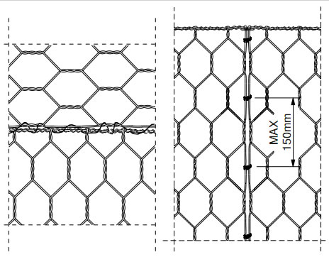
Figure 2
Figure 3
Connect the diaphragms by using either lacing wire or ring fasteners (Fig.2 and Fig.3). Ring fasteners shall not be spaced more than 150 mm apart. The procedure for using lacing wire consists of cutting a sufficient length of wire, and first looping and/or twisting the lacing wire to the wire mesh. Proceed to lace with alternating double and single loops through every mesh opening approximately every 150 mm pulling each loop tight and finally securing the end of the lacing wire to the wire mesh by looping and/or twisting. The assembly of multiple gabion units via this procedure is permitted.
Installation and Filling
After preparing the foundation, the pre-formed gabions are placed in their proper location to form the structure. Before filling the units, all corners should then be securely connected to the neighboring gabions using lacing wire or ring fasteners and following the same procedure as described for connecting the diaphragms above.
The end from which work is to proceed, shall be secured either to the completed work, or by rods or stakes driven into the ground.
These stakes must be secure and reach at least to the top of the gabion box. Stretching of the gabion boxes shall be carried out us-ing a pull-lift of at least one tonne capacity, firmly secured to the free end of the assembled gabion boxes. Tension shall be released only when the gabions are fully laced and sufficiently full to prevent the mesh from slackening.
Rocks to be used for gabions shall be hard, angular to round, durable and of such quality that they shall not break down on exposure to water or weathering during the life of the structure.
Gabion rocks shall range between 100mm and 200mm. A variation of 5% oversize and/or 5% undersize rock may be allowed, provided it is not placed on the gabion exposed surface. In all cases, the oversize rock shall not be larger than 250mm, and the undersize rock shall not be less than 80mm.
When filling, manual rock placement is required to minimize voids. The exposed faces may be carefully hand placed to give a neat, flat, and compact appearance. The cells shall be filled in stages so that local deformation is avoided. At no time, shall any cell be filled to a depth exceeding 0.3 m higher than the adjoining cell (Fig. 7).
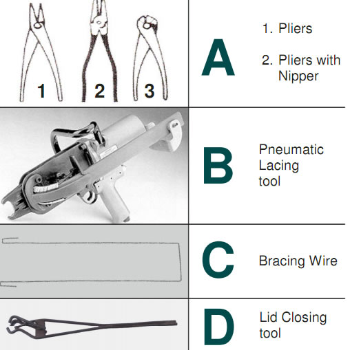
Figure 4
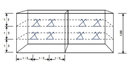
Figure 5
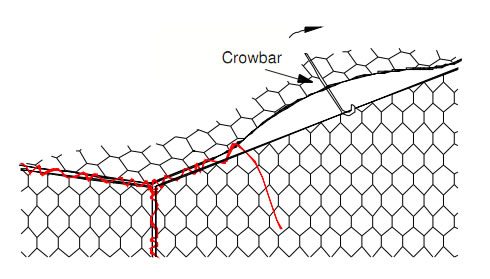
Figure 6
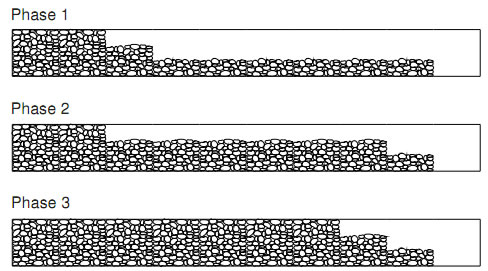
Figure 7
Care should be taken when placing rocks to ensure that the wire coating will not be damaged. Pre formed bracing wires shall be used as indicated (Fig.5), fixed at 1/3 and 2/3 of the height for 1m deep gabions to prevent distortion of the gabion units during filling and in the completed structure. These bracing wires shall be wrapped around two of the mesh wires and extend from front to back.
When more than one layer of gabions is required, in order for the individual units to become incorporated into one continuous structure, the next layer of gabions must be connected to the layer underneath after this layer has been securely closed. Placement should be front to front and back to back, so that pairs of facing lids can be wired down in one process.
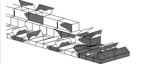
Figure 8
Closing
To allow for settlement, level off the rock fill 20-30mm above the top of the mesh. Be sure to keep the top edge of the diaphragm exposed. Fold the lid down, pull the edges of the panels to be connected where necessary using an appropriate tool such as a lid closer (Fig.4). The lids shall be tightly laced along all edges, ends and diaphragms in the same manner as described for Figure 6 assembling (Fig.6). Adjacent lids may be securely attached simultaneuosly. All end wires should then be turned in.